32
December
2014
HYDROCARBON
ENGINEERING
to reduce the SRU equipment. The acid gas enrichment works very
well where the H
2
S concentration are very low, for this project, the
H
2
S concentration for high H
2
S cases varies from 46 - 68% and the
CO
2
concentration varies from 43 - 21%, corresponding from all
cases H
2
S varies between 31 - 68% and CO
2
varies between
58 - 21%.
n
n
Acid gas enrichment is very effective where the H
2
S/CO
2
ratio is
low and will achieve high CO
2
slip. The H
2
S is enriched and SRU
unit will be smaller. In this project, there was high H
2
S/CO
2
ratio
and CO
2
slip will decline, therefore the SRU will not be smaller and
the acid gas enrichment are not very effective. In other words,
after a detailed evaluation, it was concluded that adding
conventional acid gas enrichment would be not as effective as
generally expected.
n
n
Supplemental fuel gas burning: Supplemental natural gas burning is
a technique often employed to raise the flame temperature while
processing acid gas feed of low H
2
S concentrations in a sulfur
plant. However, natural gas was not available in this project, and
using fuel gas will cause soot formation.
n
n
Oxygen enrichment: Oxygen enrichment technology is an ideal
technology for raising the flame temperature of the Claus reaction
furnace especially for acid gas of low H
2
S concentration. However,
oxygen was not available in the project.
n
n
Cooling water: Using cooling water is not practical in summer due
to hot climate weather temperature; therefore, water cooler usage
in the tail gas unit would not help in summer.
Proprietary acid gas enrichment
and SRU schemes
A unique acid gas enrichment process called Rich ‘S-MAX’ was
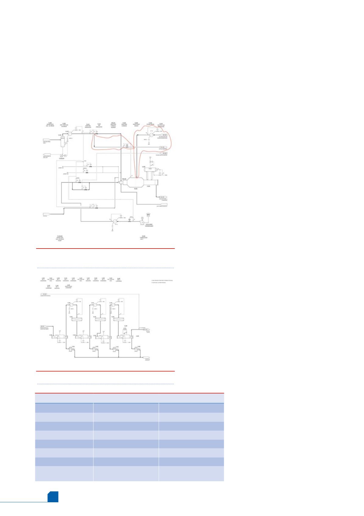
developed, and a unique proprietary scheme of the reaction furnace.
A proprietary ‘S-MAX’ two zone reaction furnace, which is different
with the conventional scheme, with high intensity burner was used. In
the conventional scheme of the two zone reaction furnace,
hydrocarbons andmercaptans will be bypassed to the second zone
where the combustion temperature would not be adequate for the
heavy impurities destruction, which will cause soot formation and
catalyst deactivation.
The combustion temperature is always higher in the first zone than
the second zone. From the above evaluation, it was concluded that we
could use exclusive schemes by RATE for the high H
2
S cases. In addition,
in order tomeet the tight stack SO
2
specification, the tail gas unit
should be designed with formulated selective solvent MDEA based
formulated solvent.
The acid gas was split from the amine unit, where up to 75% of the
amine gas entered the first zone of the reaction furnace and up to 25%
of the acid gas is routed to the tail gas absorber in addition to the
quench overhead that flows to the tail gas absorber. The tail gas amine
unit is designed with the much higher amine loading similar to the
amine unit, so in summary:
n
n
25% of the amine acid gas is sent to the tail gas absorber.
n
n
75% of the amine acid gas is sent to the first zone of the reaction
furnace.
n
n
The tail gas absorber operates at higher rich loading
(0.2 - 0.3 mol/mol).
n
n
The tail gas recycle from the tail gas regeneration unit is recycled
to the SRU but not to the first zone, instead the acid gas from the
tail gas regeneration column, which is hydrocarbon/mercaptan
free, is recycled back to the SRU. It is preheated and flows to the
second zone of the reaction furnace. The combusted gas from the
zone one reaction furnace flows to the second zone through
choke ring where the temperature is above ignition temperature,
and burn the acid gas in the second zone and the
combusted temperature leaving the reaction furnace
is 990 ˚C, according to a simulation for the high H
2
S
cases.
n
n
The tail gas absorber was designed with 0.2 to
0.3 mol/mol loading. The acid gas loading in the tail
gas absorber is normally 0.1 mol/mol maximum, and
the acid gas loading for the amine absorber is
normally 0.3 mol/mol, it means there is significant
free amine in the tail gas absorber to process the
portion of the acid gas. The tail gas absorber acts not
only as a tail gas absorber but also as an enriched
absorber without adding significant cost to the
project. This scheme also removes the
Figure 3.
Proprietary design of the reaction
furnace.
Figure 4.
Catalytic stages of the Claus unit.
Table 2.
Caustic scrubber versus conventional stack
Case
Case 1: Base case
Case 2: Alternative case
Chiller
No
Yes
Incineration type
Caustic scrubber
Stack
COS hydrolysis reactor
No
Yes
Tail gas amine circulation Lower, with higher loading Higher, lower lean loading
Recovery
99.99%
99.9%
Reliability, operability
High
Mid
Capital/operating cost
Lower (no chiller, less
power, less circulation)
Higher (chiller, more power,
more circulation)


