30
December
2014
HYDROCARBON
ENGINEERING
flash drum through a control valve to reduce the pressure prior
to entering the flash drum to separate the hydrocarbon. The
flash gas flows to the incinerator where the rich solvent flows
to L/R Exchanger prior entering the tail gas regeneration
system.
Sulfur recovery and tail gas
treating
The duty specification for the SRU represents different feed
compositions where the H
2
S varies between 31 - 68% and CO
2
varies
between 58 - 21% respectively.
BTEX/mercaptans that are removed fromacid
gas feed upstream are fed to the sulfur plant. The
low concentration of H
2
S will make it difficult for
the reaction furnace of the sulfur plant to attain
and sustain a stable flame. In addition, the high
concentration of hydrocarbons in the acid gas
feedwould require a flame of high temperature to
ensure complete hydrocarbon destruction. The
actual amount of these contaminants will depend
on the type of acid gas removal solvent to be used
upstreamof the sulfur plant. These hydrocarbon
contaminants tend to crack in low flame
temperatures, and causes carbon lay down
problems in the catalyst bed of the first sulfur
converter. Carbon laydown associated with
cracking of heavy hydrocarbons has caused a
significant number of unplanned shutdowns. A
minimum temperature of 1050 °C is required to
assure that the mercaptans are destroyed; the
RATE design reflected such requirements.
The following features are part of the design:
Three stage versus two stage
Claus
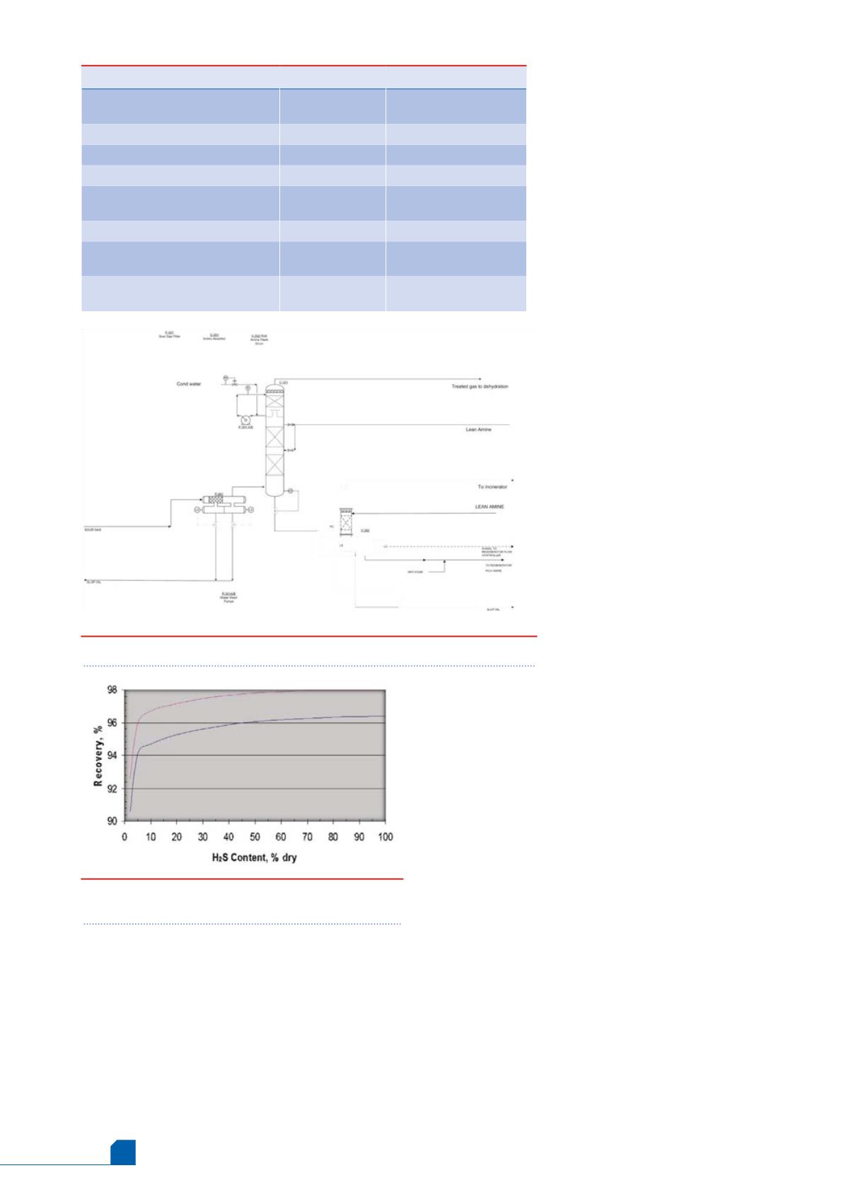
It was required to achieve 96% sulfur recovery for
all 10 cases. Due to the lean H
2
S concentration, in
order to achieve and to guarantee 96% recovery,
the calculated sulfur recovery should be above
96%; therefore, a three stage Claus was selected to
meet the recovery for all cases (Figure 2).
Start of run (SOR) and end of run
(EOR)
As the sulfur recovery operates, the catalyst ages
and become less active, therefore, throughout the
life of the Claus catalyst (4 - 6 years) the sulfur
recovery will be decrease from SOR to EOR. In order tomaintain a
reliable operation, it is normal practice to design the tail gas unit based
on EOR operation of the sulfur plant assuming more H
2
S enters the tail
gas unit.
Acid gas feed preheat and combustion air
preheat
Preheating acid gas feed and combustion air will certainly help to
increase the flame temperature of the Claus reaction furnace. However,
these design measures are not capable of raising the flame temperature
to the desired level. A combination of these techniques with another
technology is required to achieve the desired stable and high
temperature flame in accommodating the specified acid gas feeds of
various levels of H
2
S and heavy hydrocarbons contents.
Features evaluated but not used
Simulations were performed for all cases in order to achieve the
desired combustion temperature; the most cost effective option had
to be identified. Rejected features, and the reasons why these features
were not selected, were:
n
Conventional acid gas enrichment: Acid gas amine type
enrichment unit upstream of SRU common regeneration unit with
the TGU/amine unit will consist of a common acid gas
pretreatment step with selective solvent based MDEA formulated
solvent, and a three stage Claus units followed by a common tail
gas/amine tail gas treating unit, to enrich the gas to the SRU and
Table 1.
Solvent comparison
Vendor TGU evaluation
Formulated MDEA
based
Formulated
Solvent
Chemical solvent
Hybrid and other solvents
Circulation rate
TGU only, with chiller, 10 ppm H
2
S
1400 gpm
1210 gpm
TGU + partial enrichment, with chiller,
10 ppm H
2
S
2500 gpm
4900 gpm
TGU only, without chiller
1600 gpm
1450 gpm
TGU + partial enrichment, without
chiller 0.1 rich loading
2400 gpm
NA/(high)
TGU + partial enrichment, without
chiller 0.25 rich loading, 80 ppm
1800 gpm
NA/(high)
Figure 2.
SRU recovery versus number of Claus
stages.
Figure 1.
Amine unit absorption system.


