example, air has a
ε
of 1, while water has
a
ε
of 80. Most geological materials lie
within these boundaries.
Figure 1 shows the typical shape of
an ADR transmit pulse into the earth
and the received energy from the
subsurface rock layers.
ADR transmitting antennae are
optically designed using dielectric lenses
and can be referred to as behaving like
radio wave and microwave telescopes.
In the ADR transmitting telescopes, the
dielectric lens sequences amplify the
pulsed waves, but the optical feedback
provided by lasing in the telescope
chamber converts the system into an
oscillator and then into a coherent,
invisible light generator (invisible light
can be taken to mean frequencies within
the radio wave and microwave
spectrum).
An ADR beam, transmitted through
the ground, is a pulsed, confocal beam
(like a long, narrow inverted cone in
shape) of coherent (in-phase) radio
waves and microwaves. The beam
produces minimal dispersion through its
confocal and resonant mased nature.
The transmittedADR beams have two
components: a long wave-front standing
wave, which achieves deep penetration,
we well as shorter resonance waves
within the standing wave, which
enhance vertical resolution. The
transmittedADR beams typically
operate within the frequency range of
1 – 100 MHz.
The ADR transmitters must be
oriented in the same direction as the
receiving antennae. The receiving
antenna (Rx) is kept vertical, pointing
into the ground at a 90˚ look angle. The
transmitting antenna (Tx), meanwhile, is
thus moved away from Rx along the
x-direction looking at 90˚ into the
ground.
The increasing beam dispersion
through ray path move-outs can be
calculated, as can the increasing
cylindrical beamwidths, which are
plotted as the x-separation distance
increases. By simple triangulation, the
changing beam velocities through rock
layers of differing dielectrics (
ε
) can be
computed by normal move-out (NMO)
mathematics and ray tracing theory
(after Snell’s law). Because the
transmitting beam set-up is lased in the
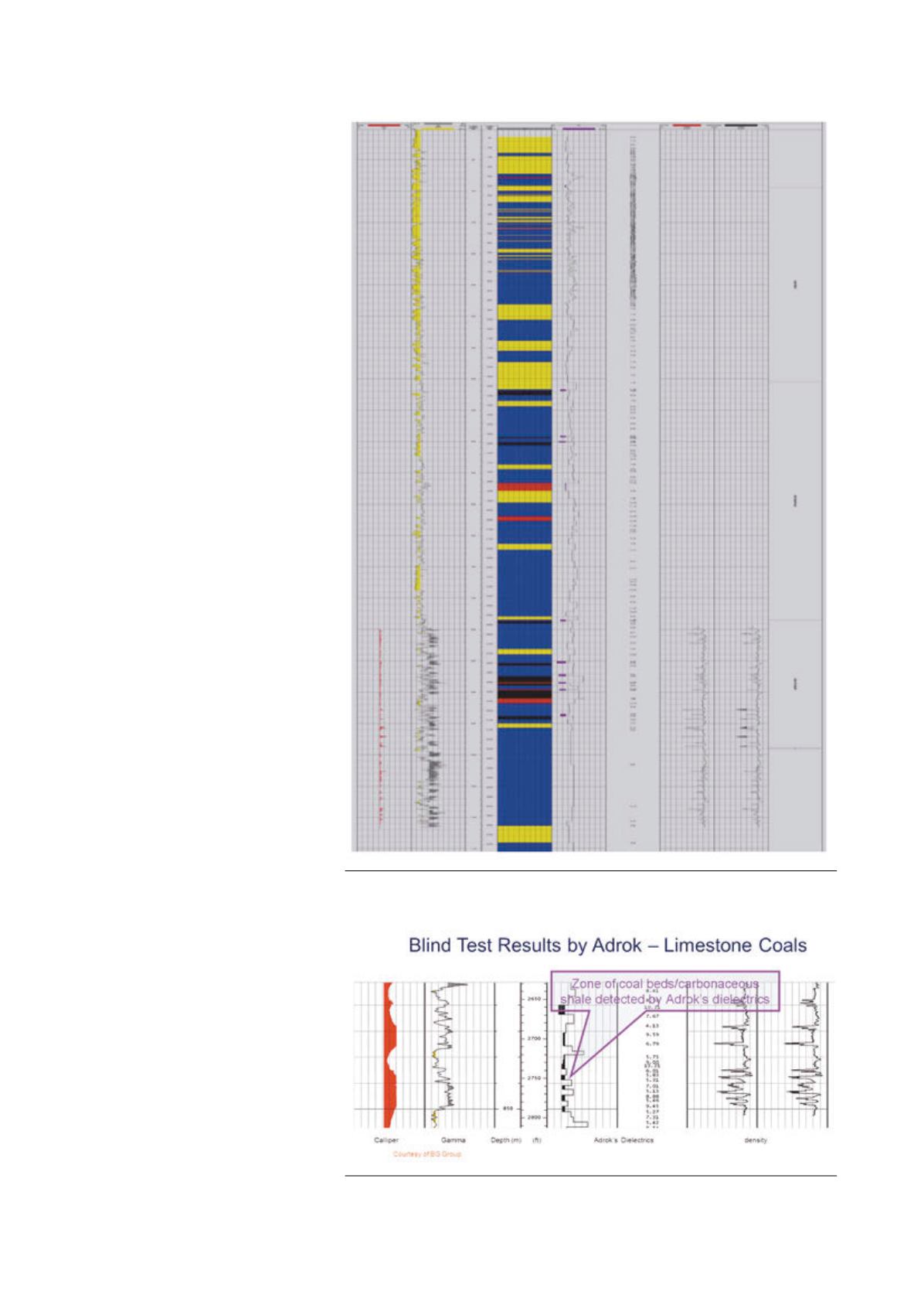
Figure 3.
ADR Surface measured lithollogical log vs downhole tool measurement.
Figure 4.
ADR Surface measured lithological log vs downhole tool measurement.
September 2014
|
World Coal
|
55


