50 |
Oilfield Technology
December
2014
steels (which tend to also attract a cost premium), as well as chemical
and erosion effects due to the proppants used.
Reducingfatigue
Fatigue cracking is generally initiated at areas of high stress
concentration, although this does not indicate yield and/or ultimate
tensile strength are governing factors of the steel. For instance, fatigue
cracking in steel can be instigated at approximately 50%of the yield
properties. With constant flexing of the stress area (such as in the case of
pressurising the fluid end), regions with stress concentration and surface
defects (e.g. machiningmarks) begin to work harden, eventually forming
micro cracks at the crystal boundaries. Continued flexing operation
propagates the cracking further until fissures are visible. At that stage, it is
only amatter of time before the component will fail.
Moreover, techniques have been specifically developed to reduce
fatigue effects, including autofrettage and shot peening. Both methods
provide localised, compressed surfaces within the internal structure
of the fluid end. Polishing the internal bores (particularly at the
cross‑section points) also aids in extending fluid end life. The smoother
surface (compared to a 63
μ
m surface machined finish) results in
decreased surface defects, thereby reducing areas in which fissures
can initiate. However, producing consistently polished surfaces can
be costly because of the significant time required to achieve desired
results.
Monoblockversusmodular
In regards to the overall design of fluid ends, two schools of thought are
currently pursued:
Ì
Ì
Monoblock design: Single, monoblock unit, comprised of a single
billet of material machined to the appropriate configuration of either
Triplex or Quintuplex.
Ì
Ì
Modular design: Interchangeable units comprised of singular fluid
ends and configured as a Triplex or Quintuplex assembly.
Replacement/repair
All bores in amonoblock design aremachined in one billet and the
pressuring function is carried out throughout the singular unit. However,
when fatigue cracking, erosion, or corrosion occur, the full unit must be
replaced/remanufactured, even if the cause is a single, problematic bore.
Turnaround time for repairs can span several weeks due to required
remanufacturing and testing processes. Operators are forced to endure
the resulting downtime on the pump unless considerable inventory costs
are allocated for maintaining sparemonoblocks.
Conversely, amodular design is focused onminimising potential
downtime by allowing for segmented replacements. With this approach,
the assemblies are created utilising singular fluid ends. Then, if one fluid
end fatigues, it can be replaced and the remaining cylinders continue
operation. Inventory options are alsomore viable, as interchangeable
fluid end segments aremore economical thanmonoblock fluid ends.
Additionally, downtime is potentially lower, as the failed fluid end is
replaceable within the assembly and the pump can be restored to
operating condition without delays for remanufacture.
Operatingconsiderations
Stresses and pressuring operations are contained within the singular
structure of themonoblock, resulting in interplay of stress distribution
across all bores. This may ultimately have a detrimental effect on the
fluid end’s overall structure. In contrast, themodular fluid end design
provides a natural break in stress distribution across the assembly.
The result is a reduction of inter‑fluid end reactions and stress transfer
between adjacent bores.
Versatility
Modular fluid end assemblies can be configured for complete
OEM replacement (i.e., all interfaces are identical to the OEM fluid end).
Operators are able to choose continued use of monoblock fluid ends
and/or modular fluid ends, depending on preference and specific
application. For example, flexibility may be preferred when known
operating conditions typically reduce fluid end life.
Maintenance
Regardless of design, a soundmaintenance programme will extend fluid
end life. Rather than mitigating pump issues as they occur, a thorough
maintenance schedule is ideal to ensure the longest fluid end life
possible. For example, it is beneficial to periodically assess fluid ends for
signs of wear and damage in areas such as the seals, check valves and
packing assemblies. The general condition of the fluid end bores should
also be examined for erosion, corrosion and/or fatigue cracking.
While specific inspection times cannot be dictated, a service
schedule or check is optimal after each frac stage, as well as whenever
feasible (e.g. during periods in which the pump is not in operation).
Proactivemaintenance aids in ensuring the fluid ends are not operated
until a fail condition that results in significant costs (especially if the
pump fails during a production operation, such as fracking).
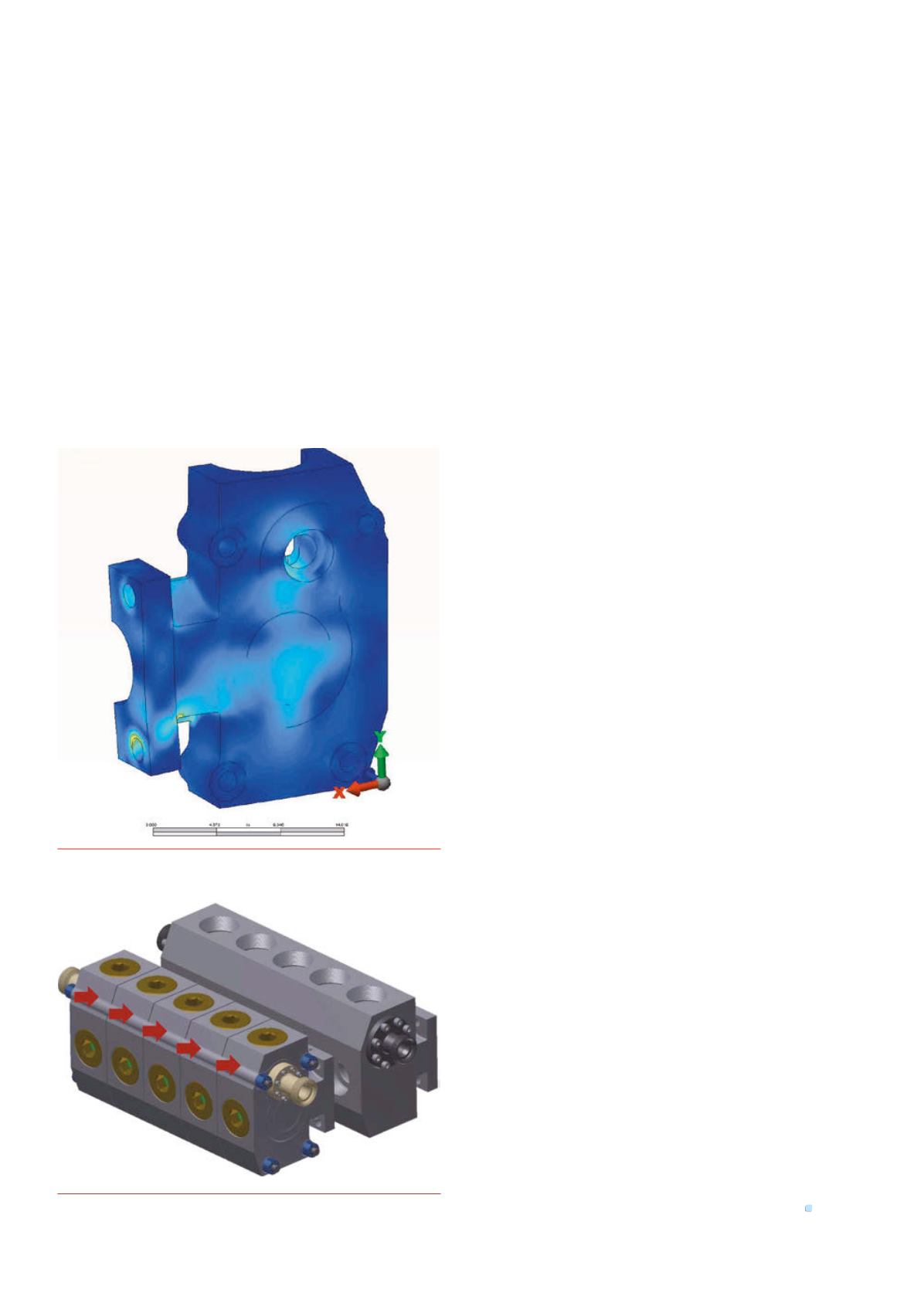
Figure 2.
FEA study conducted formodular fluid end.
Figure 3.
Modular design compared tomonoblock design.


