50
December
2014
HYDROCARBON
ENGINEERING
thus cause bubbles to collapse prior to arrival at the
impeller leading edge. ACD has specific proprietary criteria
that provide the optimum magnitude of hub rise relative to
the inducer’s axial and radial extents. The avocado shaped
hub yields the correct balance between flow centrifuging
and flow turning. The blades are attached to the front
expanding portion, and not to the aft receding portion.
Solidity is defined as the blade chord (i.e. linear distance
between the leading and trailing edges) to spacing (at the
trailing edge) ratio. The blade angle is measured from the
axial direction and must be in the 70 - 80˚ range (or 10 - 20˚
from the tangential direction). Most of the pressure rise is
produced via the centrifugal effect, while the slight overall
turning along the flow pathways produces the remainder.
The small positive incidence, usually between 0 - 3˚, is
required so that the incoming flow strikes the pressure side
of the blade. This particular design aspect is more relevant
to performance than to hindering cavitation.
The preferred impeller profile
A high performance low cost impeller is characterised by:
n
n
2D circular arc shaped blade profile.
n
n
Velocity factor = 1.2.
n
n
Blade tip back swept.
n
n
Overall blade camber < 50˚.
n
n
80%/20% head production rule.
The two dimensional (2D, with no variation along the
axis of rotation) circular arc shaped blades offer low cost
tooling, and have been proven to be efficient for
incompressible flows such as LNG.
The velocity factor is the ratio of actual impeller tip
speed to the ideal fluid pumping speed; the latter = SQRT
(H), where H is the required stage head (H). The blade
camber angle is the magnitude of the overall turning (or
curvature). The optimum blade tip back sweep angle (Beta2,
against the direction of rotation) is shown in Figure 4 as a
function of head and flow; high head low flow pumps favour
near radial tip profile, but low head high flow pumps favour
near tangential tip profile. For moderate heads and flows
the ideal Beta2 is 35˚.
An efficient impeller would have approximately 80% of
its total head produced via the centrifugal effect while the
remaining 20% produced via flow turning within the
impeller channel; this balance is essential because the
centrifugal mechanism is very effective relative to flow
turning, the efficiencies of the two mechanisms are about
90% and 70%, respectively.
The preferred diffuser profile
A high performance diffuser profile is characterised by 2D
circular arc vanes with inlet angle about 72˚ (from radial, or
18˚ from tangential), outlet angle about 45˚, and solidity
between 1.0 and 2.0; the resulting overall blade camber
angle (or turning, the difference between inlet and outlet
angles) is 27˚. In general, the preferred vane camber angle
range is from 20 - 40˚.
Consequences of fluid
incompressibility
LNG is an incompressible liquid because its speed of
sound (C, the speed at which changes in pressure are felt
within the pump stage) is very high and the pump inlet fluid
velocity (V) is usually low; therefore, the Mach number
(M = V/C) is near 0.0, far below the level (M > 0.3) at which
compressibility effects become active. At reduced flows,
the incompressible nature of LNG has two fluid dynamic
consequences.
First, the process of redistribution of flow streamlines
becomes predictable because, depending on the flow
magnitude, one of two distinct flow patterns may emerge.
At high flows only primary flow persists across the stage.
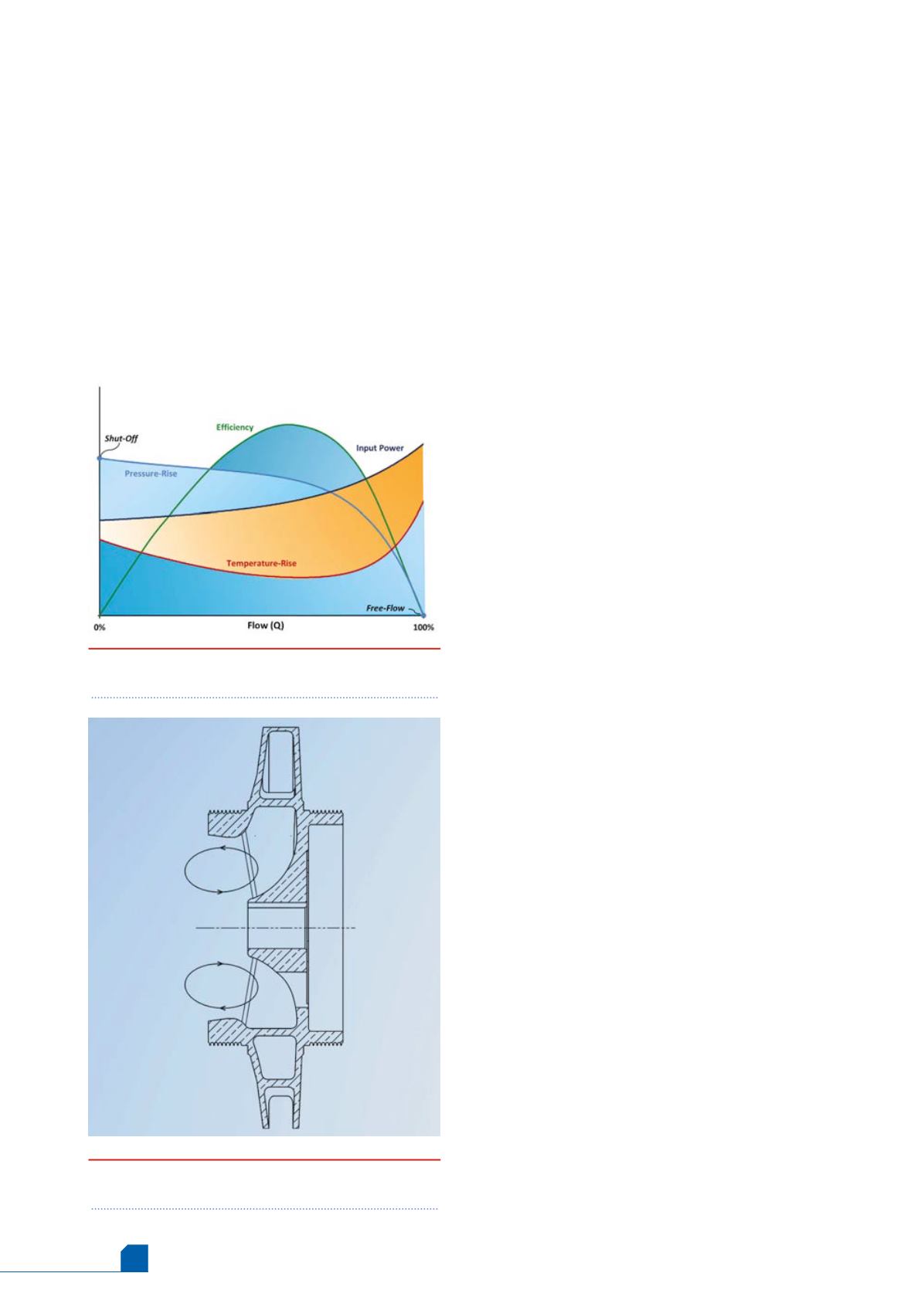
But as the flow is reduced, secondary flow begins to form,
becoming more and more coherent towards shut off, and
Figure 2.
Typical centrifugal pump performance
curves.
Figure 3.
Fully developed secondary flow
circulation at shut off.


