48
December
2014
HYDROCARBON
ENGINEERING
ships; marine
engine
conversion
projects are
creating
increased market
need for
cryogenic pumps
as primary
components of
fuel supply
systems.
Converted dual
fuel ship engines,
which consume
large quantities of low cost natural gas and small quantities
of high cost fuel oil, significantly reduce the ship operating
cost.
The structure of marine fuel supply systems depends on
engine type and includes redundant stacks of centrifugal or
reciprocating pumps. The motor driven pumps must be
efficient and reliable, and the system must satisfy vessel
maritime safety standards; fuel supply skids must be tested
and pass regulations by the American Bureau of Shipping
(ABS) and the United States Coast Guard (USCG).
The essential function of marine fuel gas systems is to
continuously provide the ship propulsion engines with
conditioned natural gas, exactly at pressures and
temperatures compatible with the dual fuel combustion
process, and at precise location and preignition time;
therefore, the need for stacked and redundant pumps. This
article focuses on the fluid dynamic aspects and design
criteria of a typical centrifugal pump stage.
General performance curves
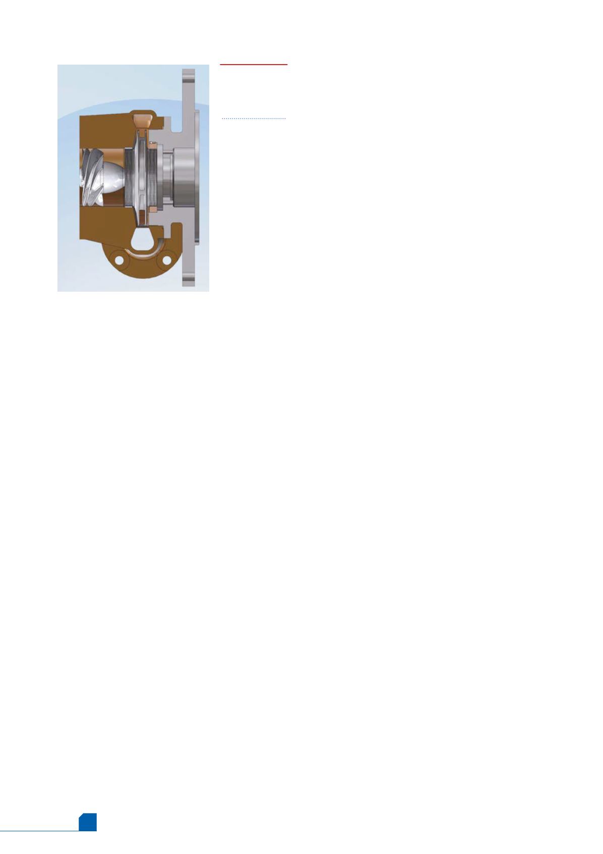
Figure 1 shows a cross section of a centrifugal pump stage,
which consists of rotating inducer and impeller and
stationary diffuser. The flow enters axially at small radii
and leaves radially at large radii, after which the
pressurised fluid is collected in a volute and delivered into
the desired port. The inducer is deployed to hinder
cavitation, while the impeller and diffuser increase fluid
pressure. Overall performance curves are shown in Figure 2
over the entire flow range, from shut off to free flow
conditions. The shapes of the performance curves may
vary, depending on the particular pump geometric and
functional parameters such as the specific speed and the
velocity factor.
The pressure rise is finite at shut off, even though the
pump net mass flow rate is exactly zero, due to established
and maintained secondary flow pattern near the inlet;
while there is no net primary flow throughout the pump,
secondary flow continuously enters near the hub and
leaves near the tip in a circulatory fashion as shown in
Figure 3. The finite power consumed at shut off, which is
not associated with any mass flow across the stage, is
required to support secondary flow circulation.
At free flow, the entire input power is consumed to
produce temperature rise only, thus heating LNG at
constant pressure and, therefore, increasing the possibility
of cavitation due to rapid sliding towards the saturated
liquid line. Also, the shape and slope of the input power
curve depends on the impeller blade profile; for example,
overloading (positive slope) or non-overloading (negative
slope) towards free flow depends on the magnitude of the
impeller blade tip sweep.
Pumping process
fundamentals
To function, all pressure producing fluid dynamic machines,
whether executing linear displacements or rotary motion,
must have a fundamental frequency generated by a driver.
Examples include the human heart, with beats per
minute (BPM) as the frequency and elastic energy (stored in
the impulse generating muscle tissue) as the driver; and ship
propellers, with revolutions per minute (RPM) as the
frequency and engine combustion power as the driver. For
centrifugal pumps, a motor causes the inducer and impeller
blades to rotate about an axis of rotation, capturing flow
proportional to RPM while producing pressure proportional
to the square of RPM. This simple trend makes pump scaling
possible and renders performance prediction accurate.
The inducer is usually utilised as a cavitation inhibitor.
Otherwise, flow separation, followed by the formation and
eventual collapse of bubbles, will likely occur near the
impeller leading edge. Research and development work on
inducers, mostly funded by the US Space Agency (NASA),
and focusing mainly on the space shuttle main engine
turbopumps, concluded that the optimum inducer must
have a rising hub contour in order to hinder the rate of
growth of bubbles as they travel downstream.
As the flow is reduced to below approximately 20% of
maximum, the usual mean flow across the stage becomes
accompanied with secondary flow cells forming near the
inlet, the secondary flow becomes more and more coherent
as the flow is further reduced. At shut off the entire mean
flow is replaced with very predictable secondary flow
pattern, and the secondary flow motion, which is sustained
via continuous supply of input power, results in finite
pressure rise across the stage. However, exactly at shut off,
the pressure rise is not considered useful because it is not
associated with mean mass flow across the stage, this why
the efficiency is zero at shut off.
The preferred inducer profile
A high performance inducer is characterised by:
n
n
Rising hub contour.
n
n
Constant tip contour.
n
n
High solidity.
n
n
Large inlet angle and slight overall turning.
n
n
Small positive incidence angle.
The rising hub and constant tip contours yield proper
area convergence (i.e. flow pathways with gradual reduction
in cross sectional area) downstream of the leading edge, and
Figure 1.
Cross
section of a
centrifugal
pump stage.


