February
2014
OilfieldTechnology
|
49
areapproximately1800ft/600m in length tocreateacustom
total length/wall thickness combinationdesigned tomeet field
requirements. This longer ribbonof steel is thencontinuously
formedandwelded intoonepieceof tubing. The strip‑to‑strip
weld is referred toas thebiasweldbecause it isweldedat anangle
relative to the strip lengthandbecomesahelix in tube form.
Thisbiasweld is important toconsider incoiled tubing string
designbecause the fatigueperformance is slightly less than the
adjacentbasematerial. Variousmethodologiesareemployedby
servicecompanies toaccount for thedifference inperformance
at thebiasweld. Acommonpractice is toderate thewelds from
10 ‑ 20%compared to thebasematerial dependingon thegrade
and fieldconditions. Regardlessof the techniqueor theamount of
derating, the slight reduction inperformanceof thebiasweldmust
be taken intoconsideration.
Oneoption tocorrect for this reduction inperformance is to
increase the thicknessof thebiasweld.
Manipulatingwallthicknessforcomplexwell
operations
Generallyspeaking, coiled tubingstringdesign formostapplications
has thicker tubewall at the topof thestring to improve theaxial
capacityandhandleahighernumberof fatiguecycles. Thebottom
of thestring is thinnerwall tosaveweightandextend reach.
Figure1showsacommonstringdesignwith0.204 in. (5.18mm)wall
thicknessat the top, and0.175 in. (4.45mm)at thebottom.
Taperedwall thickness stripsarecommonlyutilised
between thenominalwall thicknesses tomaximise fatigue life.
Figure1 includes two longer tapered strips (NotesAandB)
from0.204 ‑ 0.190 in. and0.190 ‑ 0.175 in. (5.18 ‑ 4.83mmand
4.83 ‑ 4.45mm),whichdoesoptimise the fatigue lifebetween
twodifferentwall thicknessesand transition to thinnermaterial,
but these longer transitions increaseweight and reduce theoverall
horizontal reach.
As the shapeofwellshasbecomemorecomplex, engineers
are focusedonplacing thechanges inwall thickness in the right
locationsalong the lengthof the string inorder tomaximise reach
and longevityof the string. Figure2 showsavariationof Figure1
where thebiasweldsare thicker in theuphole regionof the string to
improve fatigue (seeNoteC).With theSMARTaper technology, the
distal endsof the stripsusedduringmanufacturingare thicker than
thecentre section. Anexampleof theprofileof a strip is shown in
Figure3and theprofileof the tube is shown inFigure4.
Thecoiled tubing technology increases thewall thickness
locallyat thebiasweld,whichcan increase the fatigueperformance
toa level similar to theadjacent thinnerbasematerial. The increase
inweight at eachweld isapproximately150 lbs (68kg) depending
on thediameter andwall thickness. But the increase in fatigue
performance is substantial for theoverall string.
Anotheruse for SMARTaper incoiled tubing stringdesign is
tocut oneendof the taperoffanduse the remainingpiece to
transitionbetweenwall thicknessesquicklyas shown inFigure2
(NotesDandE). ByusingSMARTaper in the transition regions, a
controlledchange inwall thicknessoccursquicklyafter theheel
of thewell inhorizontal applications to improve reach. Thisalso
avoidshaving toweld twodifferentwall thicknesses together,
whichcreatesa steporhingeeffect and further reduction in
fatigueperformance. Theprofileof aSMARTaper stripused to
transitionbetweenwall thicknesses is shown inFigure5.Utilising
this technologyhas improveddownhole reachand improved
thedurabilityof biaswelds in theuphole sectionof the string to
improve longevityand safety.
For smoothefficientdrilling
andproduction
500K
DP2000DOUBLEFLUIDPUMPER
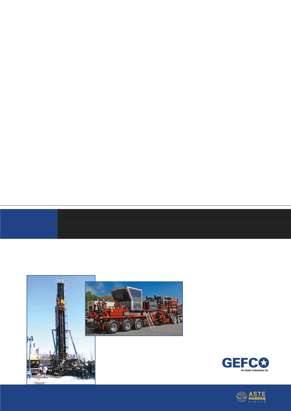
For fastmobilityand fast rig-upand rig-down, the
GEFCO500Kprovidesyour 2-3mancrew themost
efficient andeasy-to-operate rig in theworld.
For smoothproduction inahigh-
pressure, high-volumedoublefluid
pumper, only theGEFCODP2000
canprovideyouhigherpressures
forwell treatments.
GEFCO
anAstec IndustriesCompany
2215S.VANBUREN - ENID,OK73703USA–800.759.7441–580.234.4141–gefco.com


