Existing collision avoidance systems
for opencast mines rely on the distance
and direction of travel of neighbouring
equipment. Advanced systems now
use predictive algorithms to determine
whether the paths of equipment will
cross. However, given the
unpredictability of a shovel’s motion
and the need to operate very close to
clean-up equipment and haul trucks,
these systems cannot be directly
applied.
A radio-frequency identification
(RFID) based system will typically
detect when equipment or personnel
have entered within a certain distance
of the shovel. Operators are then
notified through audible and/or visual
indicators. In practice, this can become
an irritation for shovel operators, as the
geometry of the equipment is not
considered. For example, a haul truck
that is 2 m from the counterweight is
not in immediate danger; however, a
dozer cleaning debris 2 m from the side
of the shovel is within the swing path
and in extreme danger. If the system
alarms under both conditions, the
shovel operator may become
desensitised to the alarms and will no
longer give them the attention they
require. A similar issue exists with
GPS-based systems that rely on the
distance between objects.
Motion Metrics International Corp.
has developed a patent-pending
solution to the collision avoidance
problem that focuses on the smart
identification of potentially hazardous
operation. This feature is included as
part of the company’s unified
ShovelMetrics™ system, which also
integrates missing tooth detection,
tooth wear monitoring and rock
fragmentation analysis, as well as
payload monitoring capabilities. These
solutions have been successfully
installed on over 220 shovels in
50 mines worldwide.
The proximity detection component
of ShovelMetrics displays a bird’s eye
view of the shovel with the inner
collision zone and the warning zone
around the shovel to differentiate
between the two levels of danger
(Figure 2). The width of the warning
zone can be adjusted, as opposed to the
collision zone, which is entirely fixed to
the geometry of the shovel. As the
name of the warning zone suggests, the
objective is to provide an early warning
to the operator(s) involved.
The system consists of up to seven
rugged radar sensors mounted around
the body of the shovel. Mounting
locations and angles are designed to
give full coverage of the surrounding
area. Additionally, a wide angle
surveillance camera and a warning
light pair are mounted on each side of
the shovel. A central processing unit
and touch screen display are installed
within the operator's cab to provide
visual and audible alerts. An example
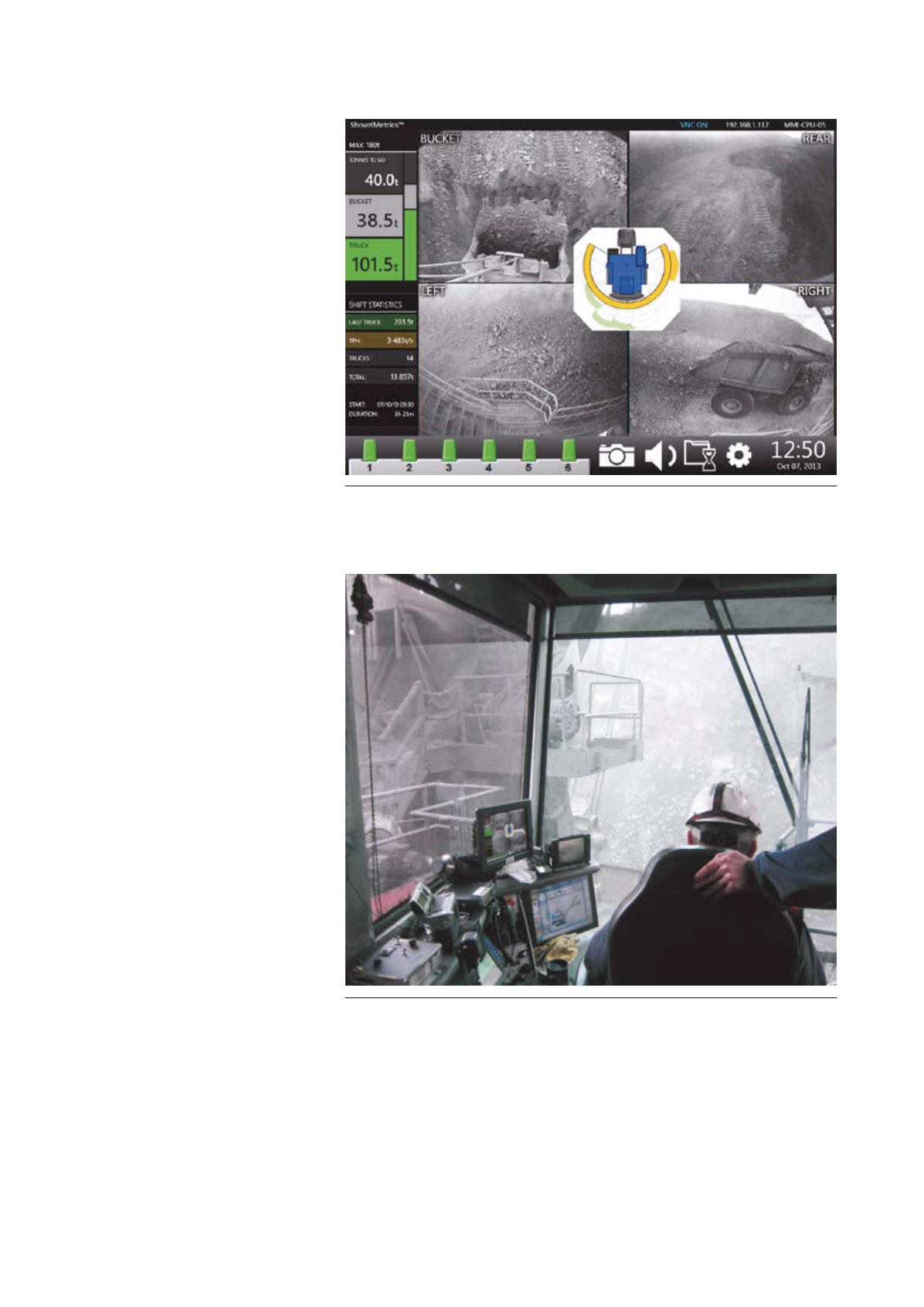
Figure 4.
Centre view: the bird’s eye view of the shovel with the corresponding radar
sensor and zone indicated. Top right view: the rear camera view of the shovel. Bottom
left view: the left camera view of the shovel. Bottom right view: The right camera view
of the shovel.
Figure 5.
ShovelMetrics proximity detection display in the operator’s cab of a P&H
rope shovel.
September2014
|
World Coal
|
31


