28 |
Oilfield Technology
December
2014
showa comparison between the previousmotor design and the newly
engineered design, in terms of rotation limitations within various
wellbore curvatures. The improvements are noteworthy and point to a
clear, over‑all, improvement in design.
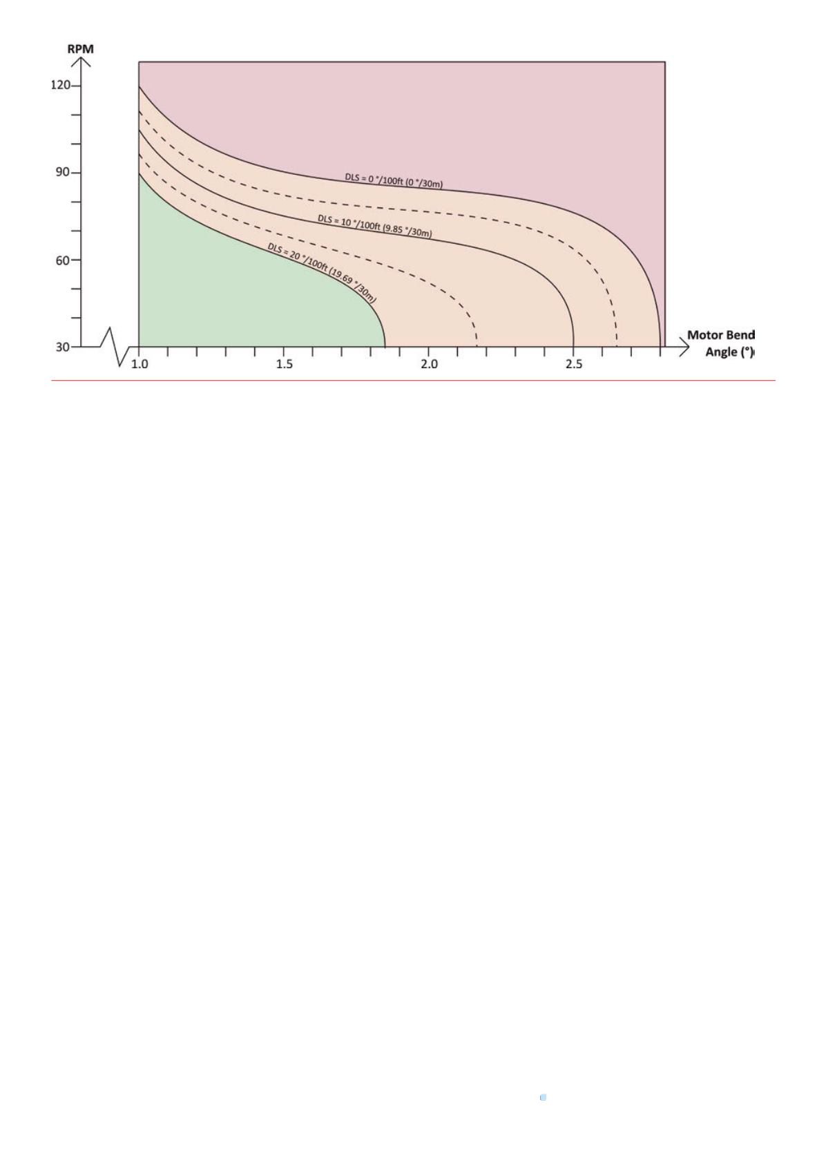
The curves in the figures represent wellbore curvatures (or dogleg
severities [DLS]) plotted against motor bend angle and drill string rotation
speed. The diagrams given are valid for slickmotor configurations
only. Corresponding to the current dogleg amotor is in, themaximum
sustainable rotation rate can be determined by findingwhere this
curve aligns with themotor’s bend angle setting. The areas between
the curves are colour‑coded to signify the severity of operating in that
configuration. The red is a ‘no‑go’ area and represents configurations that
would undoubtedly lead to amotor failure due to fatigue if themotor
were rotated for an extended period of time. The orange zone is simply
to illustrate the area of uncertainty established due to environmental
factors such as formation hardness, drilling conditions and other
parameters. Rotation in this area is sustainable as long as care is taken
while transitioning fromslidingmode into rotarymode and themotor
has not seen an excessive amount of operating hours. The green region
correlates to sustainable operation, regardless of the field being drilled.
When comparing Figures 6 and 7, it can be seen that the sustainable zone
(green) has expanded to three‑times its original area, while the caution
zone (orange) has been slightly narrowed and pushed further to right. This
inevitably results in a smaller ‘no‑go’ zone and an increased operational
envelope.
Casestudies
Optimised through advanced engineering, the improvedmotor has
yielded remarkable field results in performance and durability. Several
operators have noted themotor’s success and are seekingmore
opportunities to use it as their standard for wellbore placement. The
following case studies provide application examples where themotor
surpassed the operational limitations of previously usedmotors.
Twomile lateral inClevelandSand
The operator was looking for a cost effective alternative to running a
rotary steerable system in their extended reach laterals. They needed
to drill roughly 9500 ft in the Cleveland Sand andwere looking for a
conventional motor and BHA that was up to the task. The 5 in. version
of the improvedmotor design, with a 1.75˚ fixed bend, was able to drill
the lateral averaging over 3100 ft per run. During one 24 hour period, the
drillersmade 834 ft of hole despite rotating only 48%of the time. This was
the operator’s longest lateral drilled to date in the Cleveland Sandwith
conventional directional tools. The drilling team’s performance and
cost‑effective alternative to RSS, surpassed the expectations, received
praise from the drilling engineers and solidified using the newmotor on
future projects.
EagleFord: vertical, curveand lateral inonerun
An operator was aggressively drilling awell programme in the Eagle Ford
and pushing for safe, efficient drillingmethodologies that would complete
these challengingwells on, or ahead of, schedule. The well plan called
for a TD at 17 550 ft. Implementing the improved 6½ in. motor, the
operator was able to drill the vertical, curve and lateral sections in one run
in 150 hours, going 12 900 ft and rotating 92.4%of the time. The high
performance power section, durable titanium flex shaft, robust bearing
assembly and highly experienced crewall factored into the success of
this run. Themotor averaged 2391.6 ft/d, completed the well in 7.29 days,
saving time andmoney compared to earlier wells.
PermianBasin,Wolfcamp: 8600 ftof lateral inonetrip
The operator needed to drill a 10 205 ft lateral section of a horizontal well
in theWolfcamp formation of the Permian Basin. TheWolfcamp formation
presents an undulated pay zone of sandstone, shale and limestone, which
challenges even themost efficient drilling equipment. The new 6½ in.
motor was deployedwith a 1.50˚ fixed bent housing in the lateral. The
motor was downhole for 157 hours, drilled 8615 ft in a single run and
TD’d the well, using a PDC bit. Themotor rotary drilled 90.75%of the time
with an ROP of 98.75 ft/hr. The newmotor efficiently drilled the extended
lateral section in one run, maximising the operator’s access throughout
the wellbore for perforation and increasing production. The durability and
performance of themotor, lack of NPT and drilling the lateral in one run
saved the operator a significant amount of time andmoney.
Conclusion
The new drilling motor is a prime example of how optimisation
practices in the engineering phase, outside of field operations, can
improve drilling performance. Observable issues with equipment in the
field led to a significant redesign of motor components, resulting in a
new product. The improvements have been successfully proven in the
field with multiple operators and continue to be an effective solution
for directional drilling.
Figure 7.
Rotation limits of new6½ in. TiTAN22motor inan 8¾ in. wellbore.


