26 |
Oilfield Technology
December
2014
drilling tools to the surface, provides ameans of transporting drilling
mud downhole and transmits rotary torque to the lower drill string
components; the drill collars or heavy‑weight pipes, which deliver the
WOB necessary to push the bit into the formation; and the downhole
mudmotor, which provides ameans to steer the assembly and generates
rotation at the bit, independent of drill string rotation. The specific layout
of the lower drill string, typically referred to as the BHA, is critical to the
success of the well. The design of the BHAwill dictate how the drilling
assembly interacts with the formation, thus directly affecting steering
characteristics. In aworld of shrinking drilling targets and optimised oil
extractionmethods, controlling the direction of the well is of utmost
importance to an operator. It is the responsibility of the service company
to ensure that their tools canmeet these needs, set forth by the operator,
both in terms of performance and reliability. As the industry continues
to push the boundaries on drilling, optimisation techniques become
increasingly more important for maintaining success on each of
these levels.
The success of any well starts with themotor as themost critical
component in the directional drilling assembly. While drilling, downhole
motors are consistently exposed to high temperatures, excessive
pressures and heavy loading; even under normal circumstances these
can be limiting factors in the life of a tool. Due to a lack of observable
data regarding the types of forces and loads themotor is subjected to
downhole, development of such drilling components has been done
via a ‘Build and Test’ approach. In this way prototype designs are
iteratively tested until an appropriate configuration passes all necessary
performance and safety assessments. Unfortunately, it is impossible
to test for every drilling scenario as they differ greatly fromarea to
area, and company to company. Thismeans that issues will arise in
the field that will have to be addressed throughout the life of the tool.
Recently, there have been a number of reported incidents relating to
the non‑conformance of specific components of a particular motor.
The incidents encounteredwere primarily related to the bent housing
of themotor, and a knuckle‑joint connection that is part of the internal
drive‑train assembly.
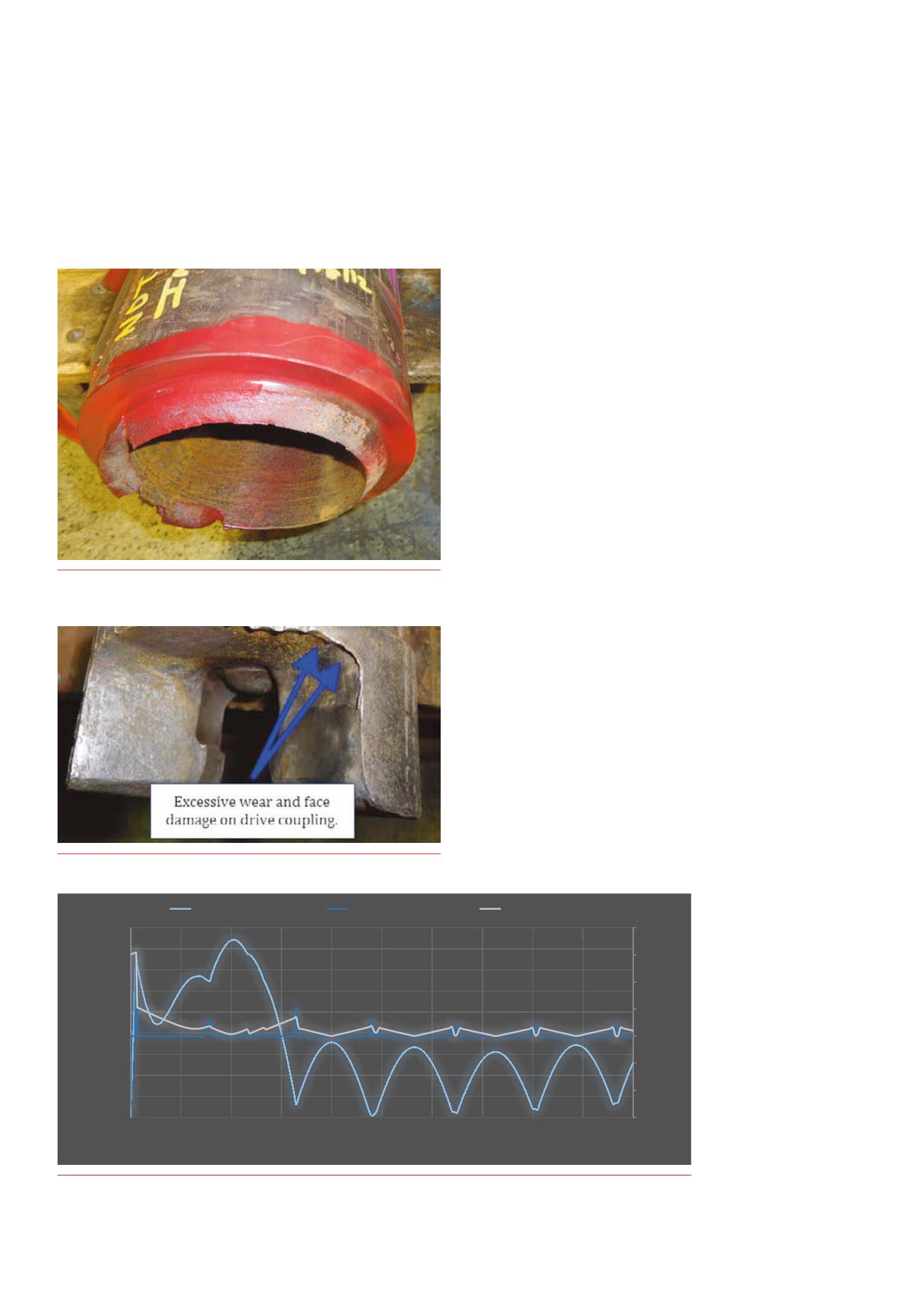
The bent housingwas observed to experience noticeable cracking
near the base of the threads on a number of runs. This suggested that,
in certain scenarios, the thread roots were stressed beyond the limits
of thematerial. In a couple of severe cases this resulted in twist‑offs
(Figure 1) of themotor and subsequent loss of motor parts in the hole.
The knuckle joint problemwas less noticeable in the field, but would
be very apparent during servicing. Visual inspection of several motors
revealed that the knuckle‑joints were experiencing excessive wear during
operation (Figure 2), most likely due to stick/slip conditions downhole.
As a result, these parts had to be frequently replaced, resulting in high
maintenance costs and, in some cases, significant NPT.
Engineeredsolutions throughcomplexmodelling
With very limited downhole data available, it is difficult to empirically
determine the forces andmoments acting on the drill string, thus it is
more challenging to design tools that handle those loads. In order to
providemore robust equipment and optimise components to survive
severe drilling conditions, this hurdlemust be overcome. Internally
developedBHAmodelling tools havemade it possible to reliably, and
efficiently, recreate these
downhole loading scenarios
and determine the effective
forces andmoments
acting on the BHA. In
post‑analysis, the drilling
scenarios associated with
a well can be examined
and realistic tool loading
can be calculated based
on what occurred during
a particular motor run.
This type of computation
provides tremendous
insights for root cause
analysis and general drill
stringmechanics.
Figure 1.
Extreme case of abent housing failure resulting in the twist-off
of amotor below the bend.
Figure 2.
Signs of excessivewear ona knuckle-joint component.
-‐6000
-‐4000
-‐2000
0
2000
4000
6000
8000
0
2000
4000
6000
8000
10000
12000
14000
16000
18000
0
20
40
60
80
100
120
140
160
180
200
Drill String Loading
Total Bending Moment (7-‐lbf)
High-‐Side Contact Force (lbf)
Total Shear Load (lbf)
Distance from Bit (5)
Total Bending Moment (5-‐lbf)
Contact/Shear Force (lbf)
Figure 3.
Estimateddrill string loading fromBHA analysis computation.


