December
2014
Oilfield Technology
|
27
Figure 3 provides an example of the predicted loads on a 6½ in. motor in a
3D curvedwellbore.
Once the loads are estimated they can be used to performmore
detailed structural analysis using intricate Finite Element Analysis (FEA)
software. FEA provides an accurate calculation of the stress distribution
throughout the body of a tool, which allows engineers to develop the best
design to handle the variation in loading parameters. This reduces
the need for prototype testing, ultimately resulting in decreased
development costs. Using this advanced analysis approach, the
recent motor incidents were examined ‘under themicroscope’.
From field observations it was clear that the bent housing had
operational limitations. All of the incidents in the field pointed
towards an over‑loading of the thread roots. Simulation of the same
field scenarios using the BHAmodelling technique suggested that
this over‑loadingwas the result of high bendingmoments at the
bent housing. Once a distinct value was reached, the bent housing
material would begin to yield. Performing an FEA on the bent housing
verified this bendingmoment limit at the thread roots, where the
stress concentrations were the highest (Figure 4). With the validated
knowledge that this loading limit exists, the component could be
adjusted by introducing stress reducing features and changing the
layout of themotor to increase the bendingmoment capacity.
Issues arising from the knuckle joint were a littlemore complex
in nature. This component is part of the internal drive train of the
motor and transmits torque from themotor’s power section to the
bit, through the bent housing and lower motor components. To
better cope with high performance power sections in long lateral
wells, it was decided to replace the knuckle joint drive with a solid
titanium rod called a flex shaft. The flex shaft provides an increased
torque capacity, for more power transmission to the bit, while
improving reliability and durability of themotor. The optimisation
of this component is critical to its success as the flex shaftmust
be strong enough to handle the torque loading from the bit, while
maintaining sufficient flexibility to properly function inside of the bent
housing. Figure 5 shows an example of the stress distribution in the
flex shaft, generated as a result of the optimisation effort to balance
these two attributes. The FEA performed helped to avoid high‑stress
concentrations andmore evenly distribute the loading throughout
themotor.
Implementing these design changes, alongwith other features,
has resulted in an entirely newmotor assembly. The improved design
can providemore torque output, andmore durability than ever before
through an increased rotational envelope. With the optimised design,
themotor can rotate at faster speeds, for longer periods of time, at
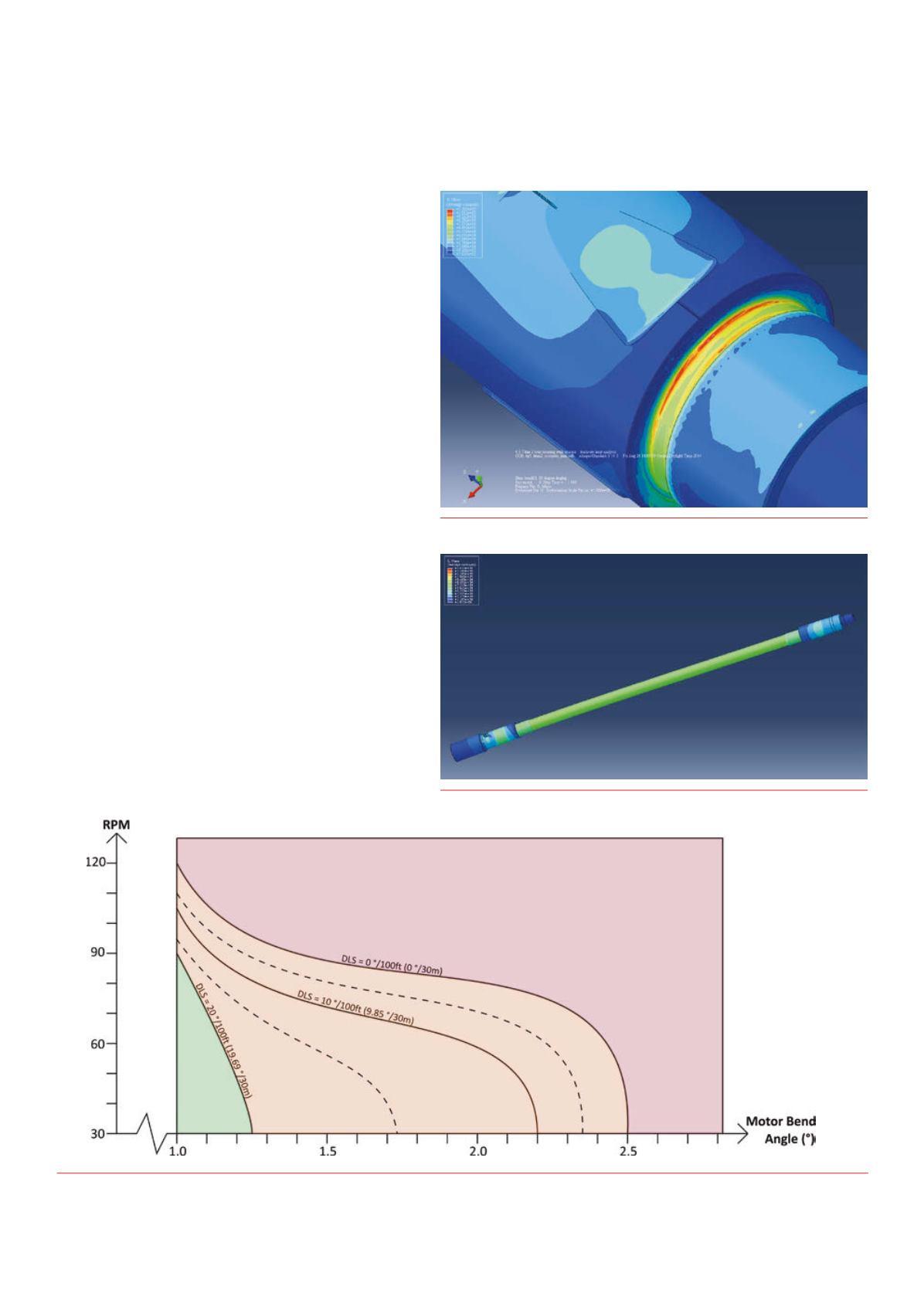
increased bend angles, in higher wellbore curvatures. Figures 6 and 7
Figure 4.
FEA stress plot of connection thread roots of TiTAN22 bent housing.
Figure 5.
FEA stress plot of Ti‑Flex flexible torque rod.
Figure 6.
Rotation limits of original 6½ in. motor design inan 8¾ in. wellbore.


