transmission line on the buried pipeline during normal (steady
state) operation.
Electromagnetic induction is due to the magnetic field
produced by AC current flowing in the phase conductors of
the transmission line, coupling with the pipeline and inducing
a voltage on the pipeline.
Conductive interference results from currents being
conducted through the soils and into the pipeline. Conductive
effects are primarily a concern when a fault occurs in an area
where the pipeline is in close proximity to the transmission
line and the fault currents in the soil are high.
If these electrical effects are great enough during steady
state normal operation, a potential shock hazard exists for
anyone that touches an exposed part of the pipeline, such as a
valve, CP test station or other above ground appurtenance of
the pipeline. In terms of personnel safety, the concern is the
voltage a person is exposed to when touching or standing near
the pipeline.
The “touch potential” is the voltage between an exposed
feature of the pipeline, such as a CP test station or valve,
and surrounding soil or a nearby isolated metal object, such
as a fence, that can be touched at the same time. The “step
potential” is the voltage across a person’s two feet and is
defined as the difference in the earth’s surface potential
between two spots one meter apart. The touch potential can
be a concern during both normal steady state inductive and
fault conductive/inductive conditions. Typically, the step
potential is a concern during conductive fault conditions due
to high currents and voltage gradients in the soil.
During steady state normal transmission line operation,
AC current density at a coating holiday (flaw), above a certain
threshold, may cause accelerated external corrosion damage
to the pipeline. In addition, damage to the pipeline or its
coating can occur if the voltage between the pipeline and
surrounding soil becomes excessive during a fault condition.
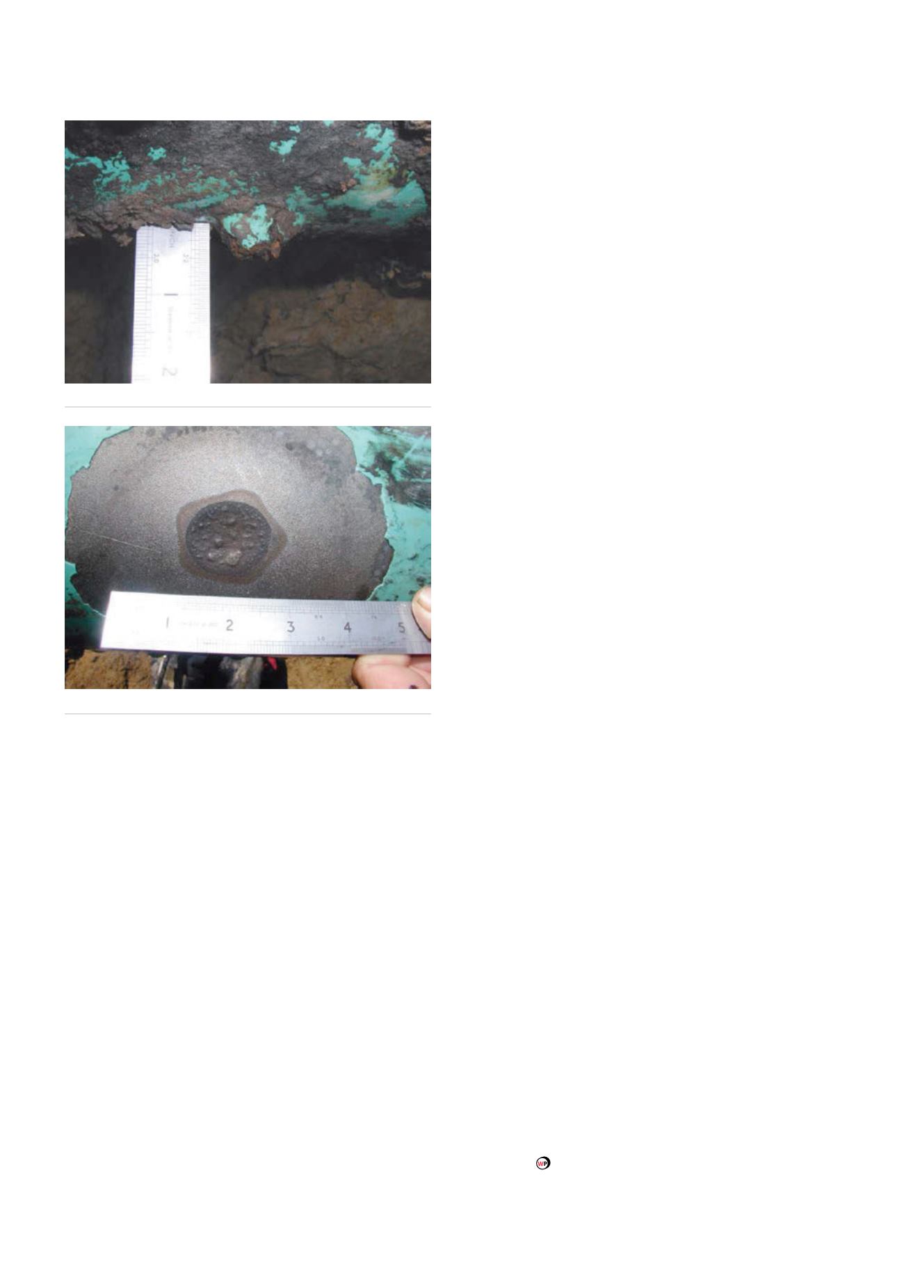
Mears Engineers have documented corrosion rates
of 2.4 mm/yr (60 m/yr) on pipelines with high quality
dielectric coatings. Examples of AC corrosion are shown in
Figures 3 and 4.
AC mitigation and the role of predictive
modelling
Induced AC safety and corrosion issues can be mitigated by
applying appropriately designed and installed AC mitigation
grounding systems consisting of horizontal or vertically
installed grounding materials. Unfortunately, many service
providers rely exclusively on predictive modelling to estimate
mitigation needs resulting in overly conservative mitigation
strategies.
Computer predictive modelling often does not account
for variations in coating resistance, depth-of-cover and soil
layering often found in the field along a pipeline. Variations
in conductor height, temperature, sag and tower geometry
over the modelled area are also difficult to account for. These
all tend to moderate the actual interference. As a result, our
experience is that computer modelling tends to over predict
the levels actually observed in the field.
Field experience and a thorough understanding of electro-
magnetic wave theory and power transmission characteristics
are required to avoid over mitigation in HVAC/pipeline
interference. Not only does over mitigation result in excess
costs, but excess mitigation grounding increases the AC
current carried in the pipeline to intolerable levels during an
HVAC line fault. This may actually increase the safety hazards
and length of the pipeline affected during a fault over more
moderate grounding installations.
Mears value proposition is to develop and implement
targeted turnkey solutions for a variety of pipeline integrity
and AC and DC interference problems. We have successfully
designed and installed AC mitigation systems for hundreds
of miles of pipelines worldwide and have done so with
designs that are based on actual field evaluations of the
electromagnetic coupling between the pipeline and the
HVAC operating systems. These designs are typically far less
cumbersome than designs resulting from predictive modelling.
Summary
Both AC and DC interference currents can cause accelerated
rates of corrosion on buried metallic piping systems. Specific
testing is required to establish where detrimental conditions
exist and to allow for the design and installation of mitigation
strategies.
Figure 3.
AC induced corrosion.
Figure 4.
AC corrosion following removal of corrosion products.
40
World Pipelines
/
SEPTEMBER 2014


